
Table of contents:
Axis-to-point azimuth measurement
Introduction
NOTE: The tools described in this article are available only for sites of the "Telecommunications" type. For more information about site types, see the "Types of sites".
Managing telecommunications infrastructure requires regular inspection of structure geometry. To make this process as simple and fast as possible, we have created a set of five dedicated analytical tools.
The set consists of tools for:
- height measurement,
- azimuth measurement,
- inclination measurement,
- axis-to-point azimuth measurement,
- verticality measurement.
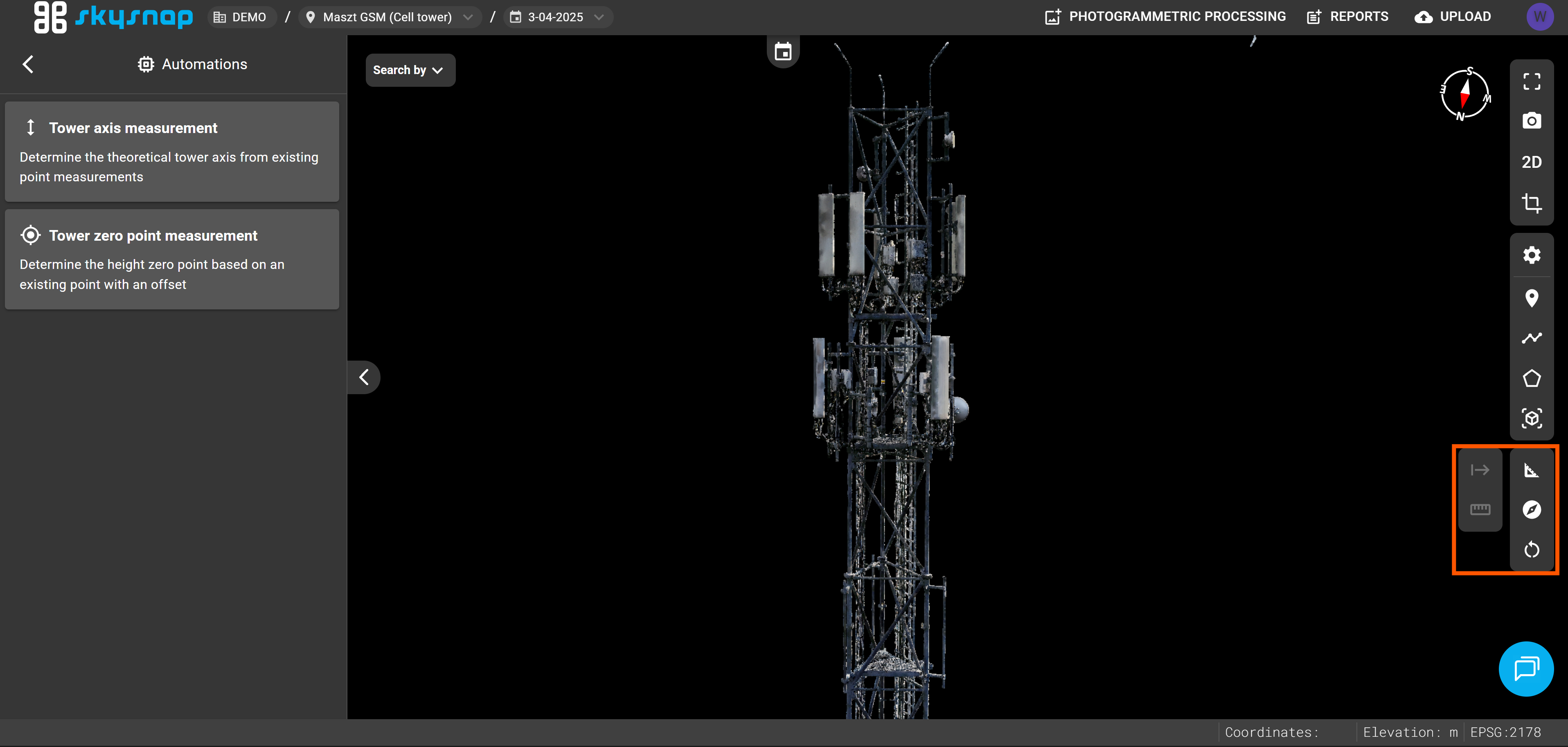
All of these tools are available from the right side panel in the 3d project view.
Height measurement
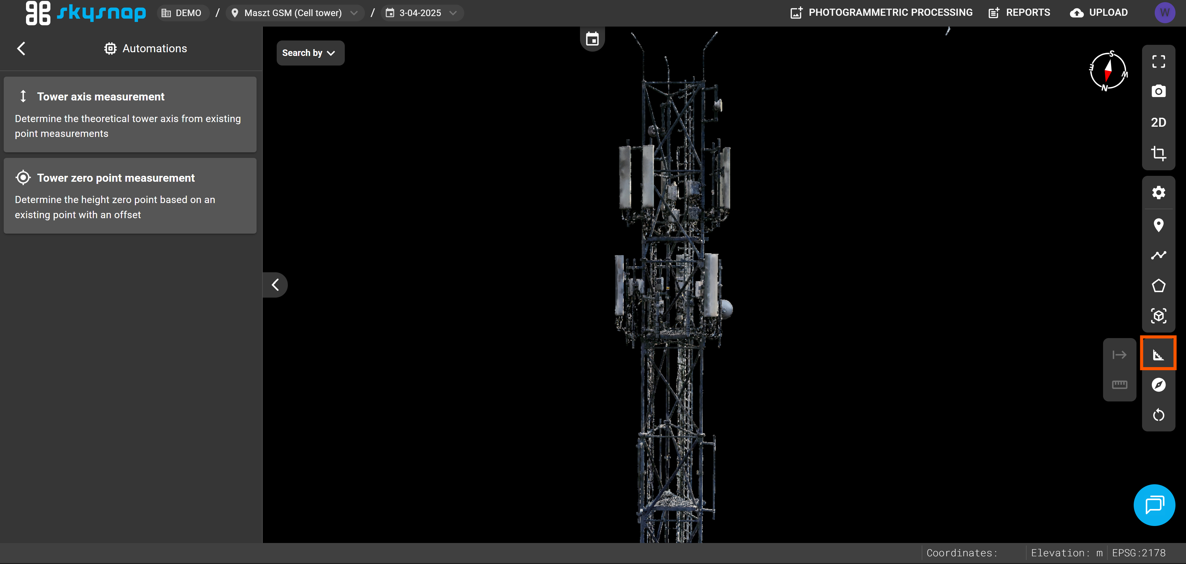
The tool allows you to determine the height difference between any two points indicated on the structure. This measurement method enables quick verification of the actual mounting distances (along the vertical axis) between elements, without the need to refer to the object's global zero level. This tool is available on the right side panel.
The user indicates a start point and an end point (e.g., the lower and upper edge of an antenna bracket, or the distance between two platforms). The result is the vertical distance Δh.
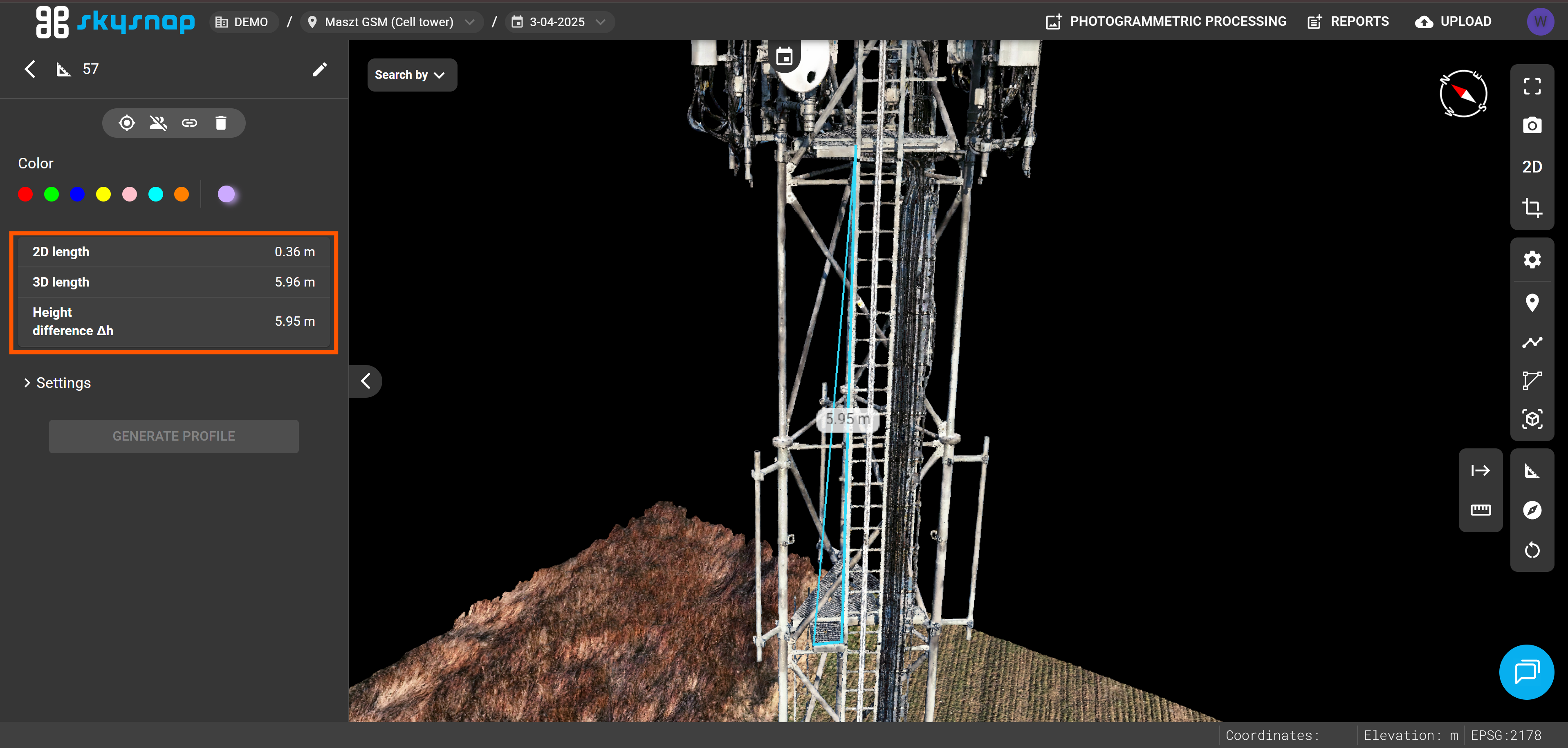
The measurement is assigned to the Lines & Cross sections folder in the Analytics tab.
Azimuth measurement
The tool allows you to determine the spatial orientation of objects based on two points. Among other things, the algorithm enables quick and convenient determination of the transmission direction of devices. The function is located in the right side panel in the project view.
To take the measurement, indicate a start point and an end point on the point cloud or 3D model, which defines the reference line.
The module returns two values:
-
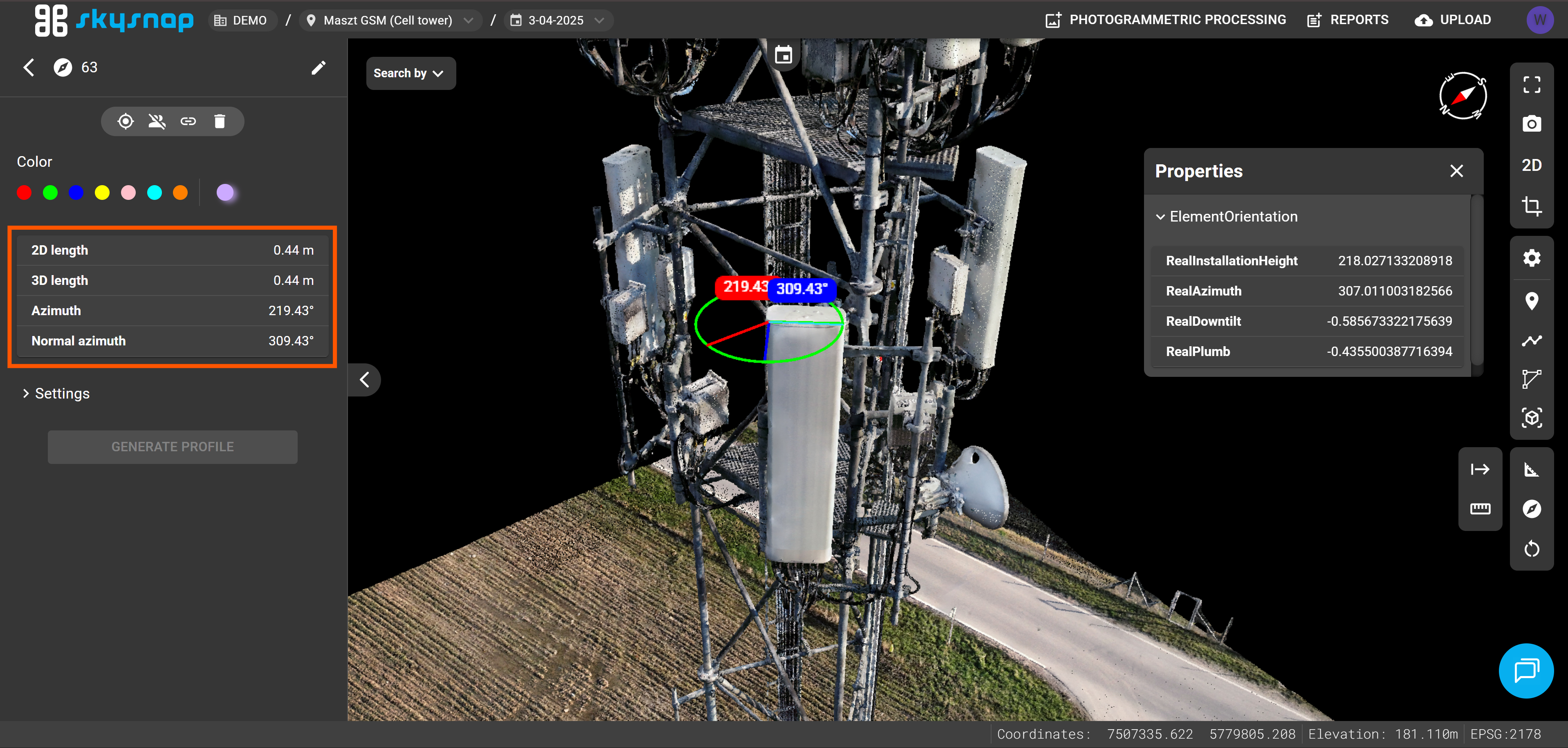
Azimuth - the directional angle of the defined line, measured from geographic north.
-
Normal azimuth - a value offset by 90°, indicating the direction perpendicular to the measurement line.
The reference line is marked in pink, and north is marked in red.
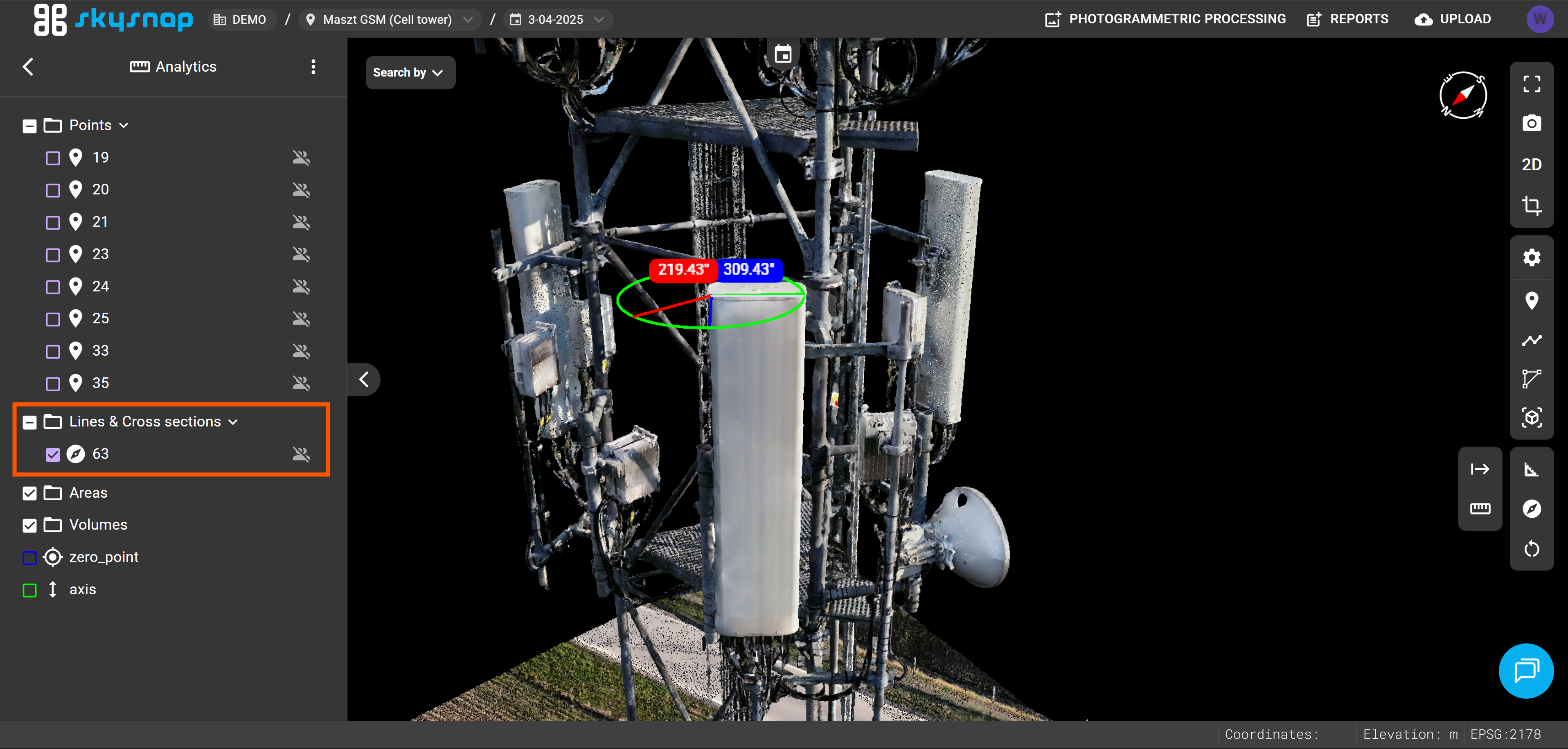
The measurement is assigned to the Lines & Cross sections folder in the Analytics tab.
Inclination measurement
This functionality allows simultaneous verification of an element's inclination relative to the vertical axis of the structure and to the horizontal line of the horizon. The tool is located on the right side panel in the project view.
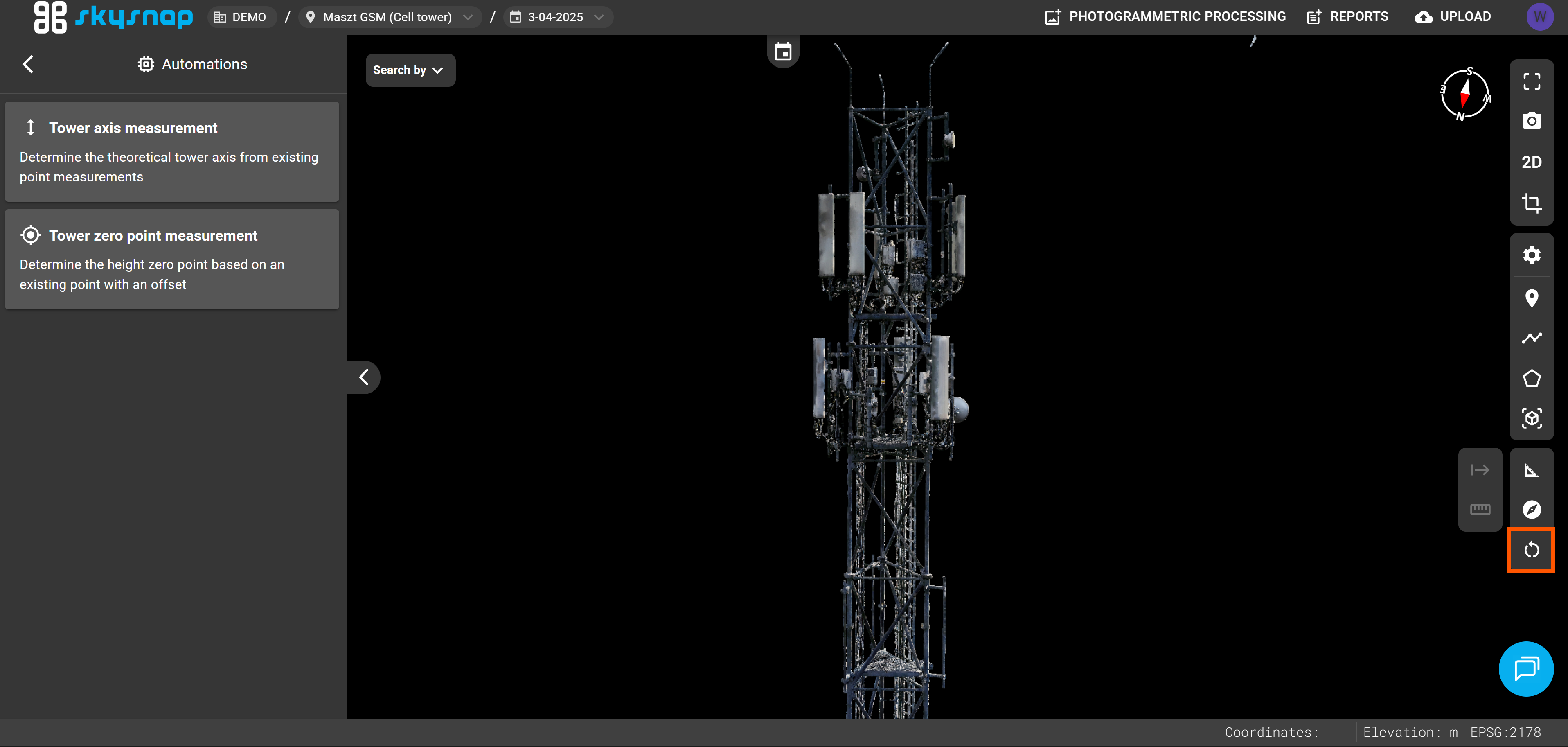
To take the measurement, indicate two points, which defines the inclination line. The module returns two related angular parameters, calculated relative to the coordinate system of the 3D scene. These parameters are:
-
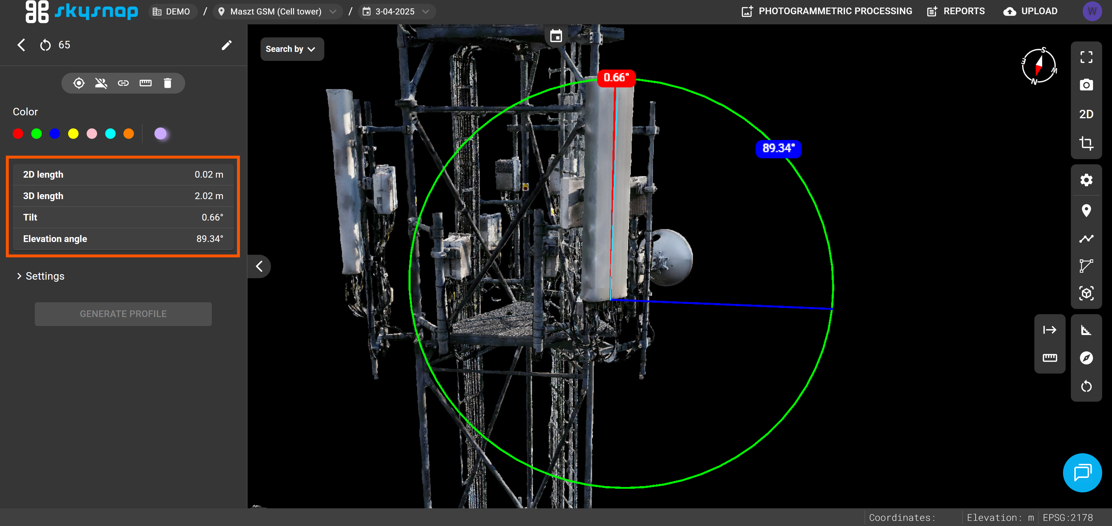
Inclination - the angle of deviation of the measurement line from the vertical (the Z axis).
-
Elevation angle - the angle of inclination of the measurement line relative to the horizontal plane (the horizon).
The inclination line is marked in light blue, and the inclination in red. The blue line represents the determined elevation angle.
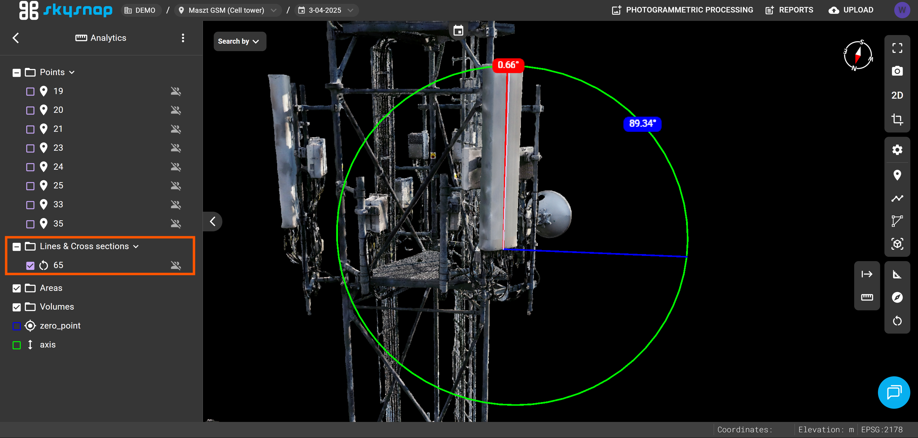
Axis-to-point azimuth measurement
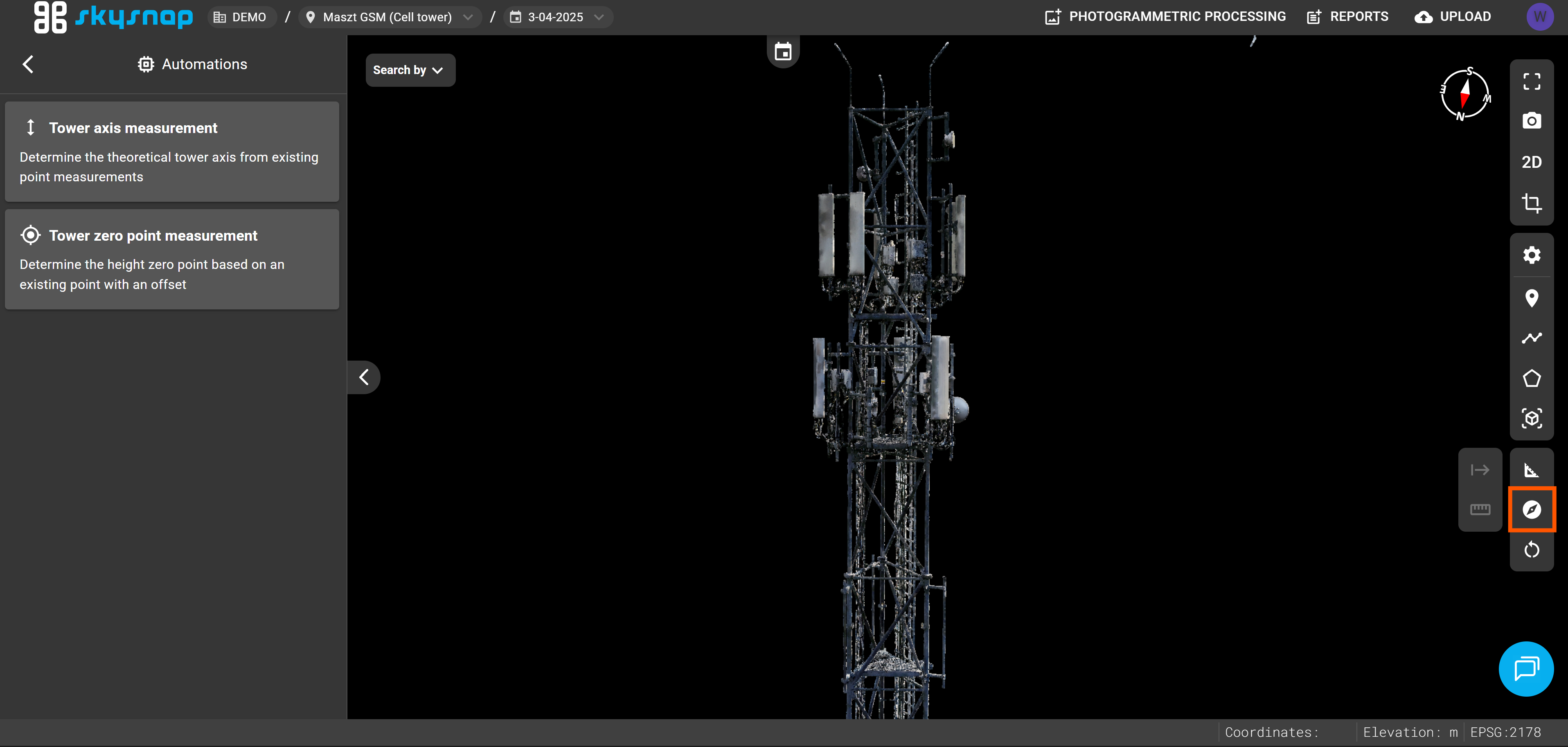
IMPORTANT: Axis-to-point azimuth measurement is available when the object's axis has been defined in the project. If no axis exists, the function is grayed out. Do you want to define an axis? See the "Telecom | Automatic determination of the tower axis".
The axis-to-point azimuth measurement determines the horizontal angle between the defined tower axis and any indicated object (e.g., the center of a sector antenna or a radio link). In the context of telecommunications towers, this is essential for checking whether the antennas transmit in exactly the direction the operator planned.
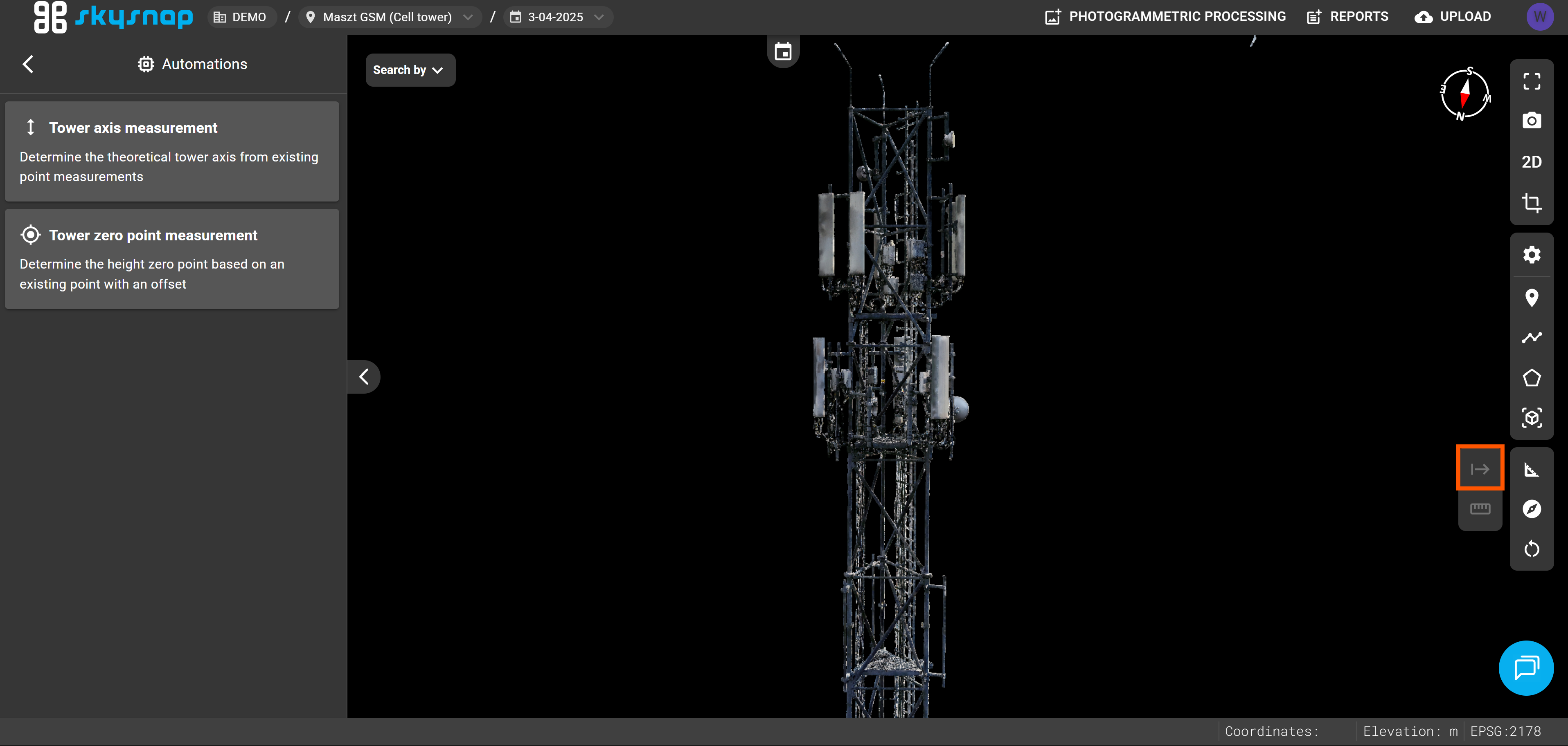
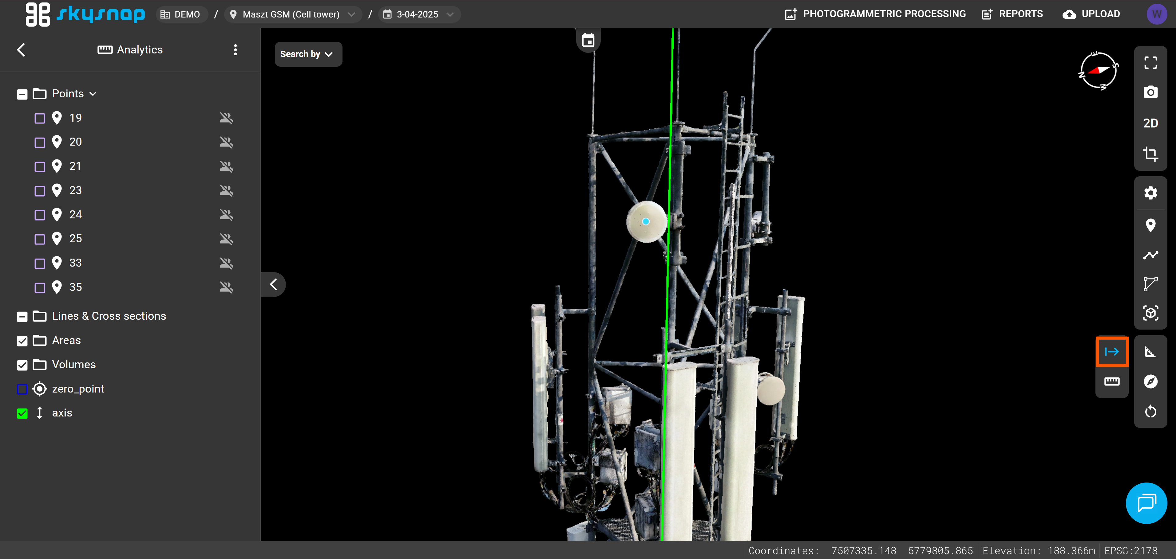
Indicate one point on the object for which you wa
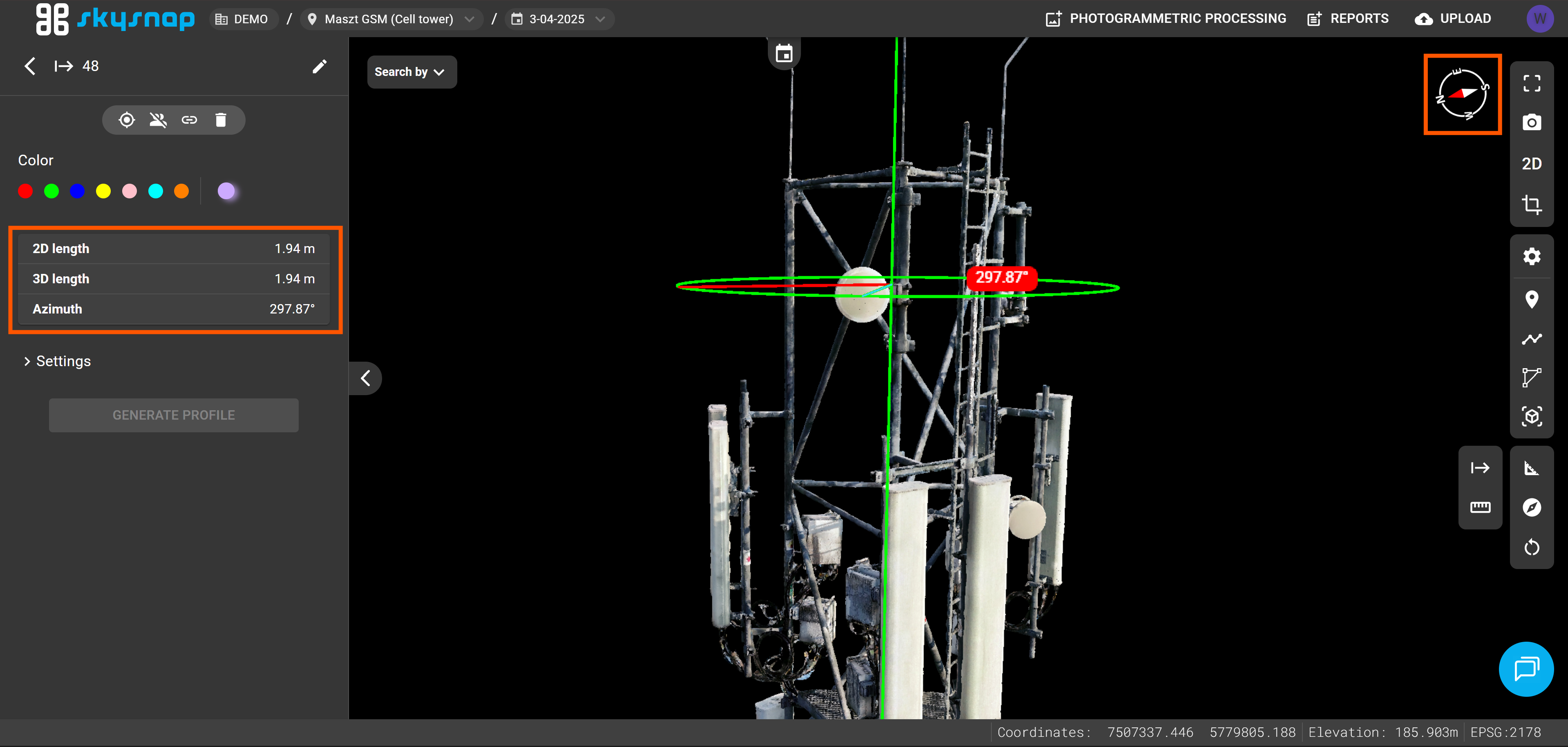
After adding the measurement, its properties tab appears, where you can read the azimuth value. The result also appears on the red label. The compass visible in the upper right corner of the view is also useful for this task.
The measurement is assigned to the Lines & Cross sections folder in the Analytics tab.
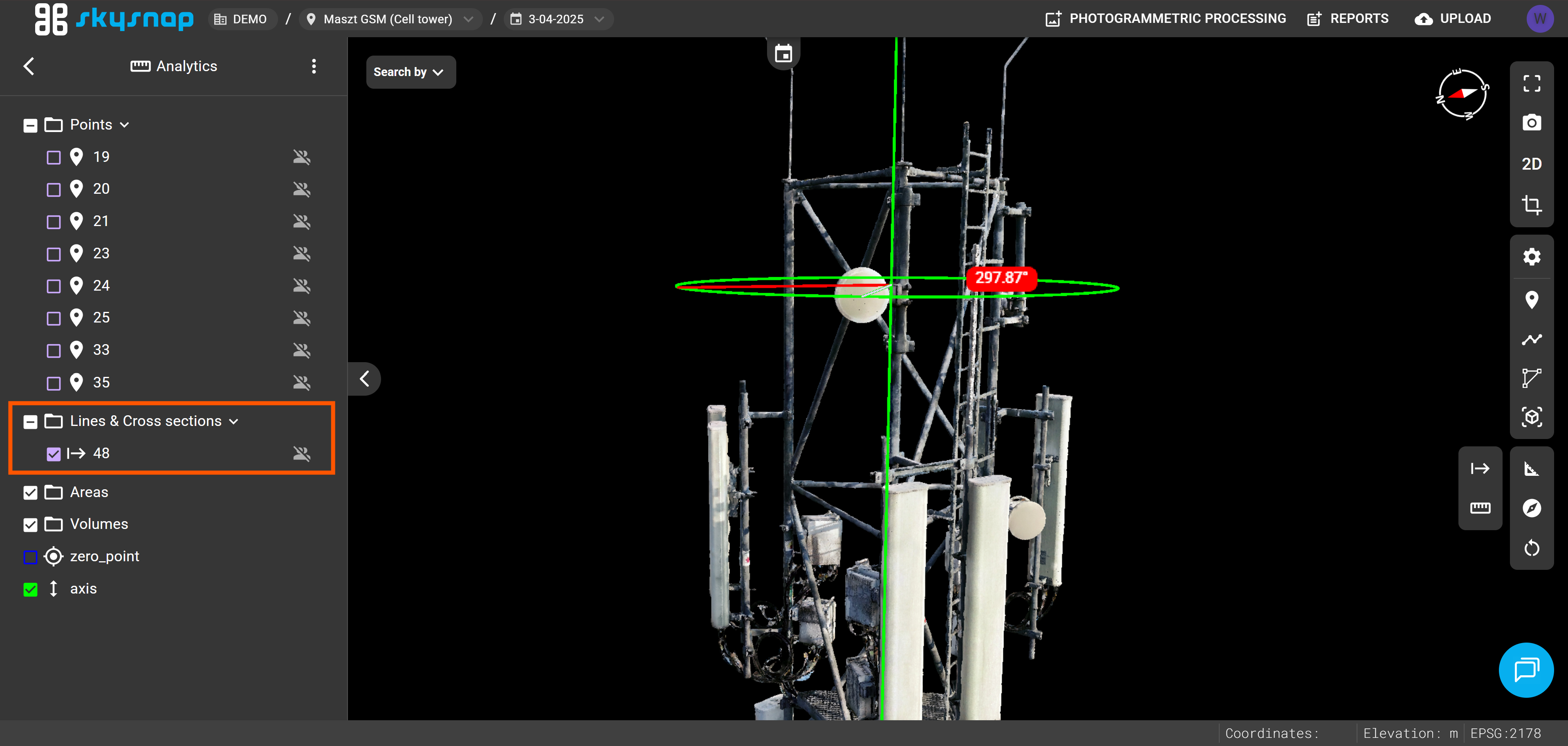
The red line indicates north, and the blue line indicates the direction to the placed point.

Verticality measurement
IMPORTANT: Verticality measurement is available when the object's axis has been defined in the project. If no axis exists, the function is grayed out. Do you want to define an axis? See the "Telecom | Automatic determination of the tower axis"
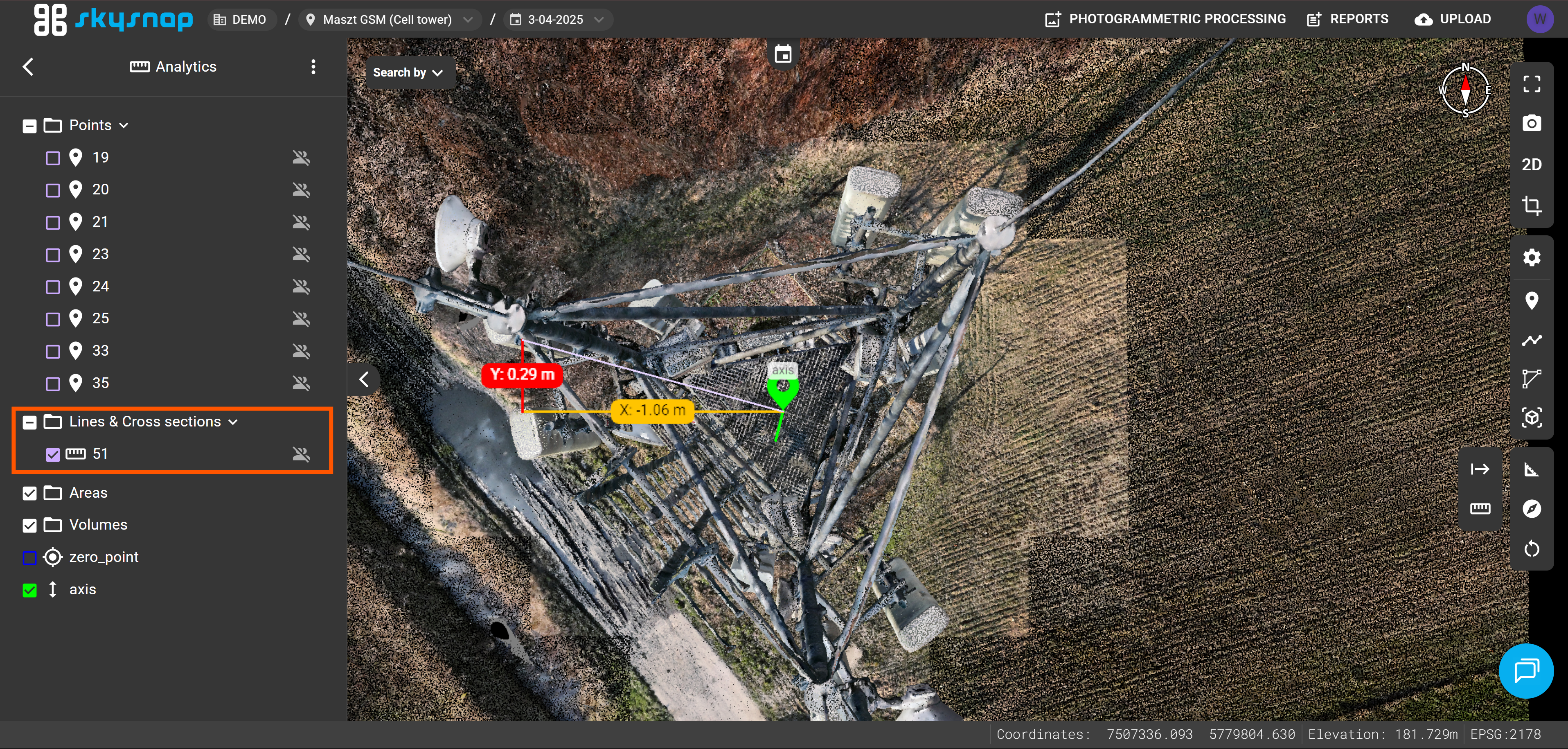
The verticality measurement module works by analyzing the deviations of a selected control point relative to the previously defined theoretical tower axis. The tool is located in the project view on the right side panel.
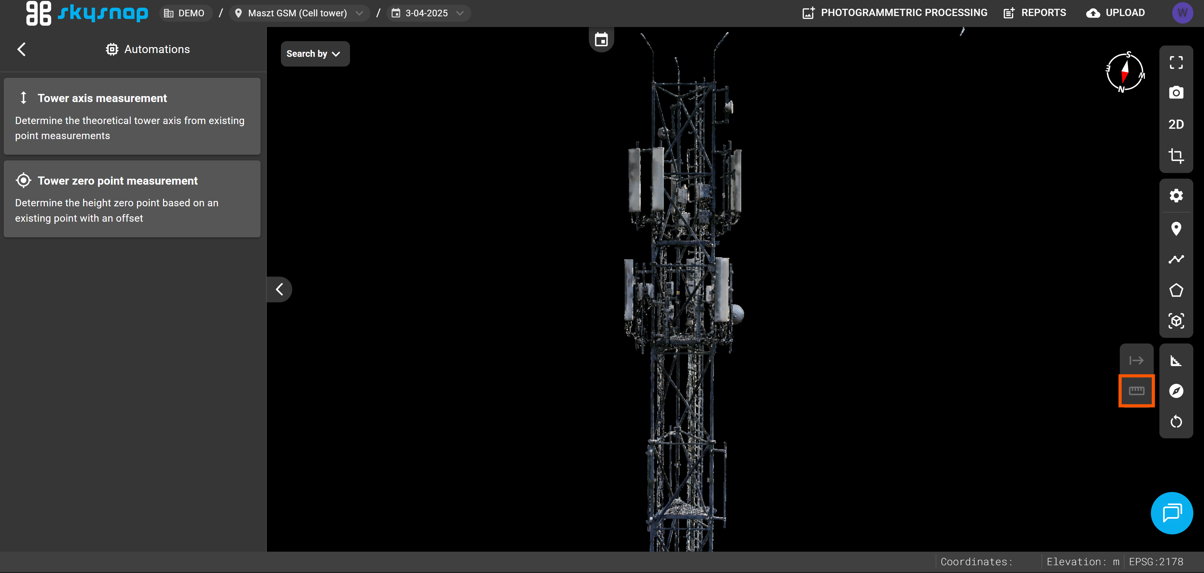
To take the measurement, indicate a location on the structure.
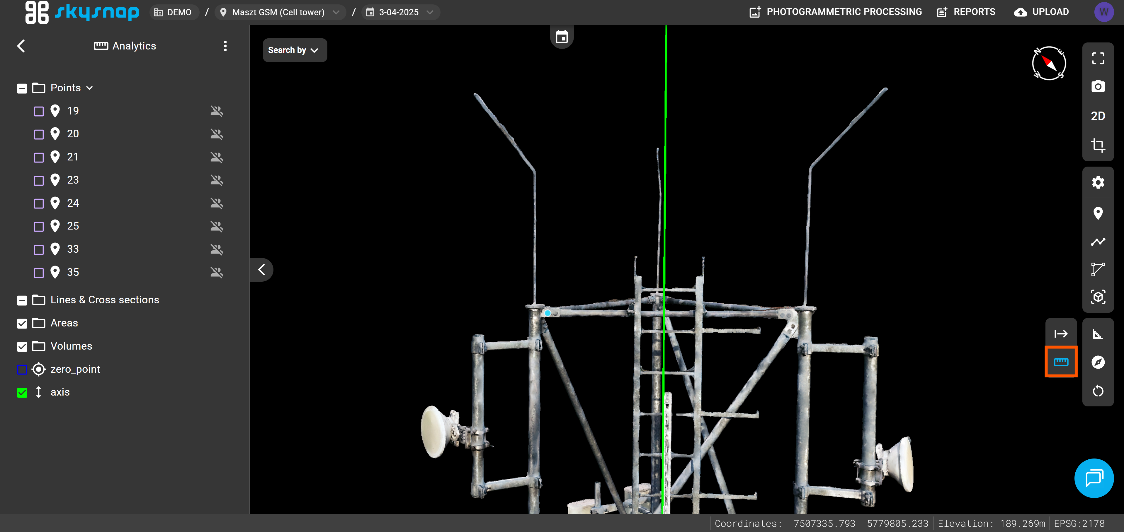
The system then calculates the distance of the indicated point from the reference axis, which is treated as the origin of the coordinate system (0,0). The ΔX and ΔY values indicate the structure's deviation from vertical along the axes of this system, allowing you to assess the local geometry of the object.
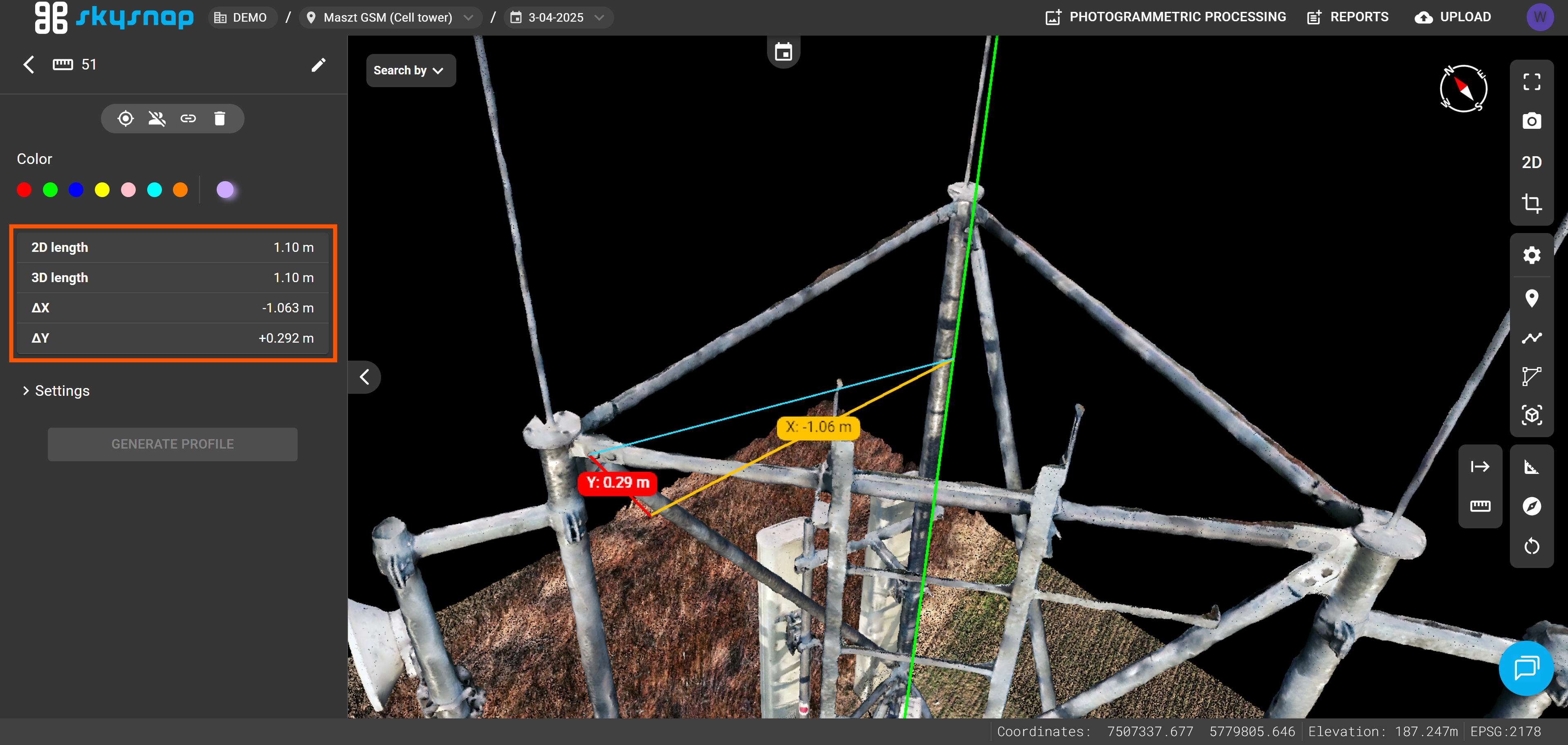
The measurement is assigned to the Lines & Cross sections folder in the Analytics tab.
TIP: For information about exporting results and changing the status of completed measurements, see the separate article: "Performing measurements".